- Introduction
 Learn
Learn- Try It
- Task
Learn
Electric Circuits
Watch GPB Segment G: Series Circuits (6:18).
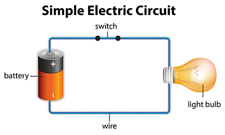
An electric circuit is a path that charges or electrons flows through.
Read Requirements of a Circuit at the Physics Classroom to learn more.
Most circuits are complex, and it's unlikely you have a device that has a simple circuit as the one shown above. There are two main types of circuits:
- Series Circuit
- Parallel Circuit
In this lesson, we will review series circuits, and then we will review parallel circuits in the following lesson. But first, let's discuss some safety measures involving the safety of circuit.
Series Circuit
A series circuit is an electrical circuit where the parts are joined one after another so that the voltage is divided among the devices in the circuit.
- A single pathway is formed for the current to flow through.
- The amount of charge that enters the device is the same amount that exits.
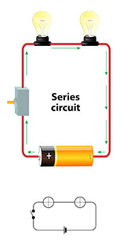
Series circuits are used in flashlights and some Christmas lights. When any part of a series circuit is disconnected, there is no current flowing through the circuit. If you've ever had a whole string of Christmas lights that wouldn't light up because one bulb burned out, that string of lights was a series circuit.
Characteristics
Since a series circuit has only one pathway through which the electric current can flow, series circuits have specific characteristics resulting from a single pathway for electron flow. Let’s investigate how a series circuit behaves with changes in voltage and resistance.
Voltage
- Go to the DC Circuit Builder (You will be using this in your lab in lesson 8.06 and this will help you practice).
- Make a simple series circuit using the plain wire and one light bulb. Once you have connected the circuit, the light bulb should light up.
- Once you have your circuit set up, click on the battery button to the left (box with a dark line through it) and change your voltage values.
- Increase the voltage of your battery.
- Decrease the voltage of your battery.
So, what can you say about voltage and a series circuit?
In terms of Ohm’s Law (I=V/R), as the voltage increases, the current flowing through the wire also increases (which leads to the brighter bulb).
Resistance
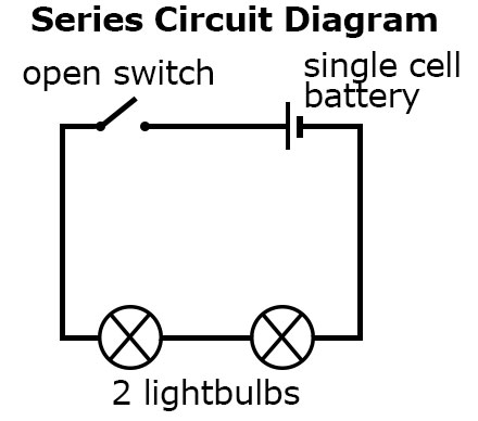
Let’s think about what happens as we change the value of resistance in a series circuit. Think about adding more resistors (like a light bulb) around the circuit, such as the one pictured below.
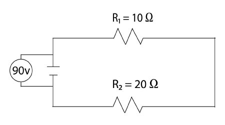
The voltage from the battery must go through both resistors to complete the circuit. Therefore the voltage is split between the different resistors. If the resistors are light bulbs, the brightness of the bulbs will be less due to the increased resistance.
In terms of Ohm’s Law (I=V/R), if the resistance is increased, then the current (I) throughout the circuit decreases. Because resistance in a series circuit increases with more resistors, this causes the current in the entire circuit to decrease when more resistance is added.
Also, as you can see in the diagram, if one bulb (resistor) goes out, the entire circuit will no longer work.
Circuit Symbols
You will need to be familiar with the following circuit symbols and diagrams to complete tasks in the next few lessons of this unit. You draw these in your notebook or print the image.
Circuit Symbols
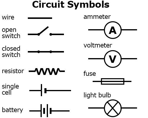
These symbols are used in creating diagrams of different types of circuits. These symbols can be used in diagrams of series circuits and parallel circuits.
Series Circuit Diagrams
Review the following links before continuing:
- Circuit Diagrams: Make sure you can identify all of the circuit diagram symbols
- Series Circuits: Read the section and complete the Exercise.